In the last months, I've got access to a Qidi X-Max FDM 3D printer. Since this is the first 3D printer to which I have direct access, I've spend some time in figuring out how it works and which problems it might have - and then trying to solve some of them.
The following notes are not meant as a tutorial - so please don't perform the steps and expect to still have a working 3D printer afterwards. Instead, it is just a public documentation for myself and might provide some pointers to people trying to work on this kind of printer.
General Problems
The Qidi X-Max has (in my eyes) various flaws:
The closed source Firmware is missing state-of-the art features and is partially incompatible with their own slicer (like the acceleration/jerk control but even simple things like M118 // is not working)
heated bed is not flat and printer doesn't have an ABL sensor nor support for manually created bed mesh
according to their support, it is also not possible to use a BLTouch because their V4.6 board is missing the trace for the Level S (actually control) pin to the STM32
maybe the 0.2mm ("one layer height) difference between center and edges of the bed is only a problem on this specific device. I am waiting for a replacement part at the moment
both extruders have various problems
many reports of clogging problems when printing with full metal hotend (and you are not supposed to use it with PLA and similar materials)
full metal hotend is shipped without part cooling fan (and doesn't seem to be supposed to be used with a fan)
extruder is a single gear design (which might cause other problems I am seeing)
normal extruder is still using PTFE liner direct to the nozzle
quite a lot of oozing for a direct drive design even with larger retractions
print quality is always switching between blobbing and under-extrusion
chamber is not insulated well enough to print slightly more advanced materials (stable) at their expected ambient temperature. So you might need to find easier to print filament blends when printing anything more complicated than ABS... at least of larger prints
chamber doesn't even have a temperature sensor
part cooling fan shroud is unidirectional which results can easily result in print quality problems depending on the orientation of a model
Qidi is (at the moment) not actively working together on upstream Cura (from which their slicer was forked) to natively support their printers
backlight of the touchscreen seems to be a thing which tends to break. I've experienced the problem a couple of days after the device was received and attributed it to the flex cable which seemed to have been attached at an angle in the connector by Qidi. But after reading a little bit in the forums of elektrifiziert.net/ it seems like I am not the only one which had a dark touchscreen after a while. But Qidi seems to send our replacement parts after contacting their support
the design of parts seems have stopped before the interactions of various components was evaluated. A good example is the flat cable to the toolhead which bends down after time and is then chewed up by the x-belt
the electronic compartment is actually part of the print chamber and not insulated. So you will heat up the MCU+PSU (and maybe a RaspberryPi you have in there) when you use the heated bed. And if you need to swap the extruder (or parts of the extruder) and a screw falls down, you often have to open the lid on the bottom of the enclosue to search for it next to the motherboard and PSU
if you bought an X-Max a couple of years ago and then buy it today then you will get two different devices - without Qidi being open about the different version/revisions
support is a mixed bag
they can be super helpful (like sending replacement parts) after a couple of mails with photos of problems
but they also sometimes just ghost you
their hard "photo" requirement is rather disturbing. Especially when you report a software problem after a firmware update (2.29) that causes regular (wave/pulse like) speed changes of the extruder heatsink fan. I've sent audio recordings in my first mail but was still asked to send a photo of the problem - I never found out how this can be done
often questions (especially about HW) are not understood and answered with phrases like "firmware doesn't support this"
You can still improve the situation in case you already have this printer and cannot switch to something more reliable like a Prusa printer (which is actually more expensive - especially when requiring a chamber). Here are some mods I've added:
Alternative part cooling fan shrouds for the original extruder:
Improve the chamber insulation (slightly):
Top Cover to close the enormous hole in the acrylic cover
Adding some insulation foam (the foam is the interesting part here. For example with tesamoll Heater reflector foil)
Flat cable guide to reduce the risk of the x-belt colliding with the cable of the toolhead
Hygrometer to at least be able to guess if the chamber was heated up enough to start a print
Dial gauge holder to simplify the bed screw based bed leveling
RaspberryPi velcro mount to have an easy way to mount the RaspberryPi which connects via the TTL pins to the mainboard. It is running OctoPi/OctoPrint as print server
Camera + LED mount to control prints from a different room via Octoprint
Alternative Carriage with different Extruder gears and Hotend. I've used a Dragon hotend with Orbiter 2 and solved the major oozing and extrusion problems I had before.
Preparation of firmware switch
While the previously mentioned modifications could solve or at least reduce some of the flaws, there was still the problem of the odd printer firmware. There is no official support in any of the common open-source firmwares for this printer (or Chitu mainboard V4.6), I've checked out which one has the most promising features and might allow me to easier (+faster) change the firmware configuration during the evaluation period. At the end, I've tried only Klipper because it has support for the used STM32F407 MCU and Funkton seemed to have been able to get it working.
But during the initial research, it became obvious that the display needs to be replaced because Klipper is not able to communicate with the Chitu proprietary interface. Also other components need to be mounted (temporarily) to the Icarus carrriage for calibration purposes. So I've designed some adapters to have them ready when switching to the new firmware and bought the respective hardware
Waveshare 5inch DSI touchscreen adapter as RaspberryPi display
ADXL345 accelerometer attachment to perform the resonance compensation calibration
BLtouch mount as auto bed leveling sensor. But you have to get a little bit creative to find a way to control it because the Chitu V4.6 board has a hardware bug (and is missing the trace from the Level-S pin of the flat cable to the STM32F407)
Identify Connectors-to-MCU mapping
Unfortunately, I was not able to get access to Funkton's Klipper configuration and was not able to find a ready-to-use printer.cfg for the Qidi X-Max (more about this at the end of this section) when I started to work on it.
The task was basically to use a multimeter with continuity checker and resistence measurement capabilities. Additionally, you should have some breadboard with some 2kOhm resistors (Qidi seems to use 10kOhm resistors as pull up/down resistors often) (which you can temporarily put on/off the the endstop pins) to be able to check easily whether you are now connected to (lets say for now) same VCC via pullup or to your actual endstop.
It is also important to identify gates of the MOSFETs (here PT50N06) because they are actually connected to the MCU (and not the source or drain). And of course, the datasheet for the STM32407 in its LQFP144 packaging is needed. The interesting figure can be found on page 43. Just don't get confused by the writing on the actual chip - it doesn't indicate the orientation. The little circle on the chip is between pin 1 and 144. The Large one is between pin 72 and 73. So you could say that the figure is rotated 90 degree counter clockwise when you would use the letters on the chip as reference.
The stepper motors are also not connected directly. Instead, the connection to the stepper drivers has to be measured and not the path to the stepper motors.
MCU |
connector/function |
note |
|---|---|---|
PE3 (2) |
Zmin endstop extruder |
2-pin JST-XH connector with label S -). It is also connected to the "Ext" endstop on the mainboard (thanks to Matthew Joffe for this info). |
PE5 (4) |
stepper_x step |
|
PE6 (5) |
stepper_z1 endstop (low active) |
|
PC13 (7) |
stepper_z endstop (low active) |
|
PC14 (8) |
stepper_y endstop (low active) |
|
PC15 (9) |
stepper_x endstop (low active) |
|
PF0 (10) |
stepper_x enable (low active) |
|
PF1 (11) |
stepper_x direction |
|
PF3 (13) |
stepper_y direction |
|
PF5 (15) |
stepper_y enable (low active) |
|
PF9 (21) |
stepper_y step |
|
PF10 (22) |
case LEDs |
MOSFET Q9 |
PC2 (28) |
bed heater thermistor |
analog input |
PA5 (41) |
stepper_z enable (low active) |
|
PA6 (42) |
stepper_z step |
|
PB1 (47) |
extruder step |
|
PB2 (48) |
bed heater (low active) |
|
PF13 (53) |
extruder direction |
|
PF14 (54) |
extruder enable (low active) |
|
PF15 (55) |
stepper_z direction |
|
PG0 (56) |
extruder heater |
|
PG1 (57) |
wifi module reset |
|
PB10 (68) |
wifi module RX |
|
PB11 (70) |
wifi module TX |
was bridged to Vcap on my board (had to by manually fixed by removing the solder bridge on the MCU) |
PB12 (73) |
heater sensor NSS |
spi2, unused? |
PB13 (74) |
heater sensor CLK |
spi2 |
PB14 (75) |
heater sensor MISO |
spi2 |
PB15 (76) |
heater sensor MOSI |
spi2 |
PD12 (81) |
stepper_z1 step |
|
PD13 (82) |
heater sensor spi2 CS |
|
PG4 (89) |
stepper_z1 direction |
|
PG7 (92) |
chamber fans |
MOSFET Q11 |
PA8 (100) |
beeper |
|
PA9 (101) |
UART TX |
|
PA10 (102) |
UART RX |
|
PA13 (105) |
SWI7 |
|
PA14 (109) |
SWC |
|
PD7 (123) |
part fan |
MOSFET Q4 |
PG10 (125) |
power LED (board) |
|
PB6 (136) |
extruder heatsink fan |
MOSFET Q15 for both motherboard fan and extruder heatsink fan |
PB8 (139) |
(unsoldered E1_HOT connector) |
MOSFET Q5 |
PE0 (141) |
power module |
needs to be set immediately to high on MCU init (and low to shutdown) |
PE1 (142) |
power button |
input |
??? |
Bed Level sensor control pin (pwm) |
seems like S pin of the 3-pin JST-XH with label S - + was not correctly connected to the MCU on the V4.6 board. Please ping me if you find some information how to still use it |
There are three directly MCU connected Pins PG1 (57), PB10 (69), PB11 (70) which can be accessed when removing the (useless) ESP8622EX based WiFi module. I've used for example PB10 as control pin for the BLTouch which I've installed.
                   WiFi
+------+------+------+------+
| VDD  | PG1  | VDD  | PB11 |
+------+------+------+------+
| PB10 | GND  | NC?  | GND  |
+------+------+------+------+
|                           |
|                           |
|                           |
|    ESP8266EX              |
|                           |
|                           |
|                           |
+---------------------------+
(please use this WiFi related pin names with a grain of salt because I was only searching for directly MCU connected pins and didn't check further for pull-up/downs, larger resistors, ...)
After searching for some more information about the temperature sensors used in the Qidi X-Max, I've found naxan6's Klipper configuration for the X-Plus with the Github search (but for some reason not via google). I highly recommend reading it and would wish that I found it earlier when I've searched for ready-to-use printer configs for the Qidi X-Max. But still, now I was able to use it to clarify some of the questions I had. I still have a slightly different opinion about some parameters.
Most of the differences can be explained by the slightly different printers. I would therefore recommend to save your original Qidi configuration to an USB-Stick with the gcode M8512 config.gcode, translate it via deepl (or similar service) and then convert the values to the units used by Klipper. But you can use naxan6's or my configuration as starting point.
Software installation
The Klipper software can be installed on the RaspberryPi running OctoPi. The necessary steps are well documented by the official documents and it doesn't make sense to provide (easily outdated) documentation at this point:
The only additional modification I had to do was to uninstall the (currently) broken fbturbo and restart klipperscreen:
sudo apt remove xserver-xorg-video-fbturbo
sudo systemctl restart KlipperScreen.service
I have also uploaded the various configuration files I've used to get support for my modified Qidi X-Max - please read the previous section to better understand why this might not match your printer.
Hardware installation
The initial step is of course to remove any power to your Qidi X-Max and your RaspberryPi.
Serial connectivity
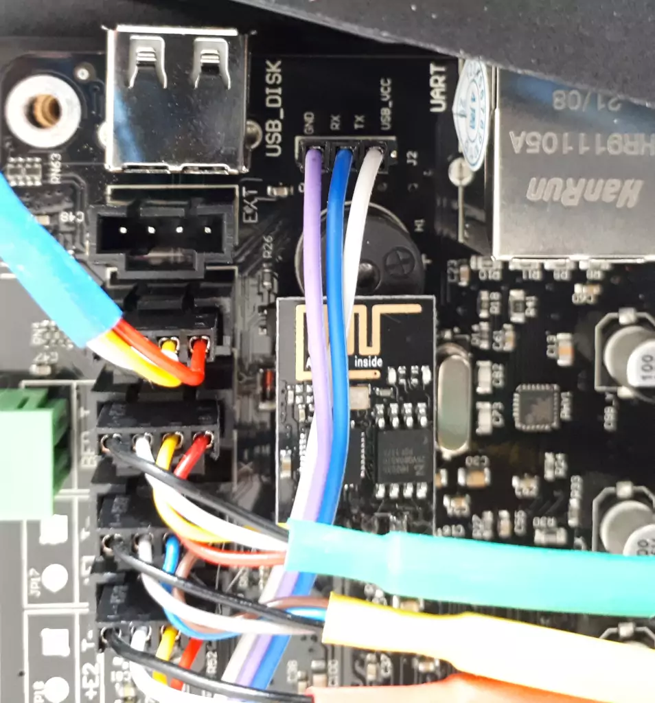
You can now connect RaspberryPi UART to the UART (J2) on the V4.6 board:
V4.6 board |
RaspberryPi |
|---|---|
GND |
GND (Pin 9) |
RX |
TXD (Pin 8) |
TX |
RXD (Pin 10) |

It is also necessary to enable it on the RaspberryPi by starting raspi-config and selecting:
Interface Options
Serial Port
Disable login shell
Enable serial port hardware
Connecting ST-Link
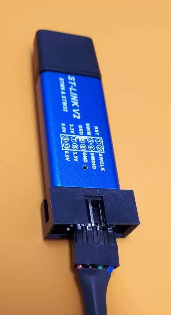
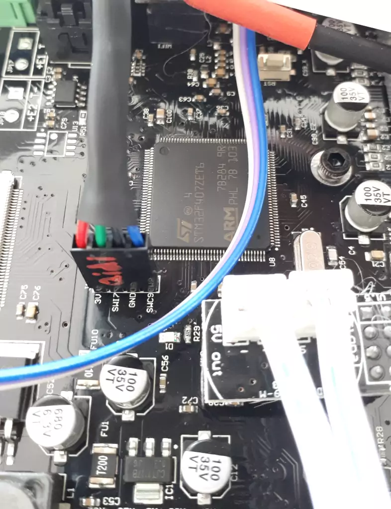
The firmware must later be flashed with an ST-Link v2 and STM32Cube. The first step is to prepare the wires and to connect it temporarily to the (powered down) Qidi X-Max.

The naming on the ST-Link is slightly different that what you see on the board. When you prepare a cable, make sure that you can easily distinguish the various wires. On one end you need to swap the center wires:
V4.6 board |
ST-Link |
|---|---|
3V (red), Pin 1 |
3.3V (red), Pin 8 |
SWI7 (green), Pin 2 |
SWDIO (green), Pin 4 |
GND (black), Pin 3 |
GND (black), Pin 6 |
SWC9 (blue), Pin 4 |
SWDCLK (blue), Pin 2 |

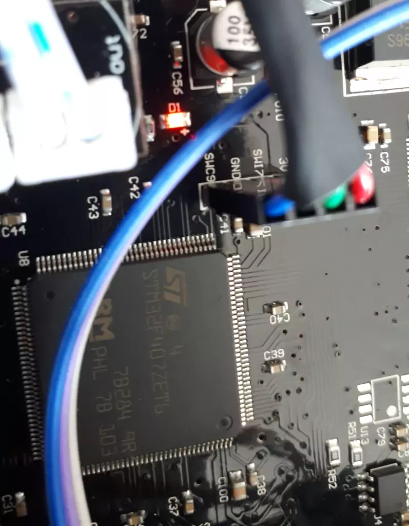
Please double check that there is currently no power connected to your X-Max (or RaspberryPi) and that you correctly connected the ST-Link to the X-Max. Whenever you will then connect the ST-Link to the USB of your host system, the red D1 LED should be lid. This means that the MCU now has power and it is possible to use STM32Cube to connect to it:

Backup of Qidi Firmware
After starting STM32Cube on your host system, perform following settings have to be used on the initial screen:
ST-Link configuration (on the right site):
Port SWD
Frequency: 4000 kHz
Mode: Under reset
Access port: 0
Reset mode: Hardware reset
Speed: Reliable
Shared: Disabled
Device memory (in the main view)
Address: 0x08000000
Size: 0x80000
The RST must be pressed (don't let it go yet), the Connect button in STM32CubeProgrammer must be pressed and then the RST button must be released immediately.
The green "Read" button can be pressed to read out the memory and the arrow next to it can be used to save the content to a file. Make sure you've backup this file.
If you want to restart the printer, please make sure to remove the ST-Link first from the V4.6 board.
Flashing of Klipper on MCU
The Klipper MCU code has to be compiled on the RaspberryPi. The important settings in the ~/klippper/.config for commit d725dfd309e3 ("screws_tilt_adjust: Added Support for M6 Screws (#6287)") are:
CONFIG_LOW_LEVEL_OPTIONS=y
CONFIG_MACH_STM32=y
CONFIG_MACH_STM32F407=y
CONFIG_SERIAL=y
CONFIG_STM32_FLASH_START_0000=y
CONFIG_STM32_SERIAL_USART1=y
CONFIG_INITIAL_PINS="PE0,!PG10"
After it was checked and saved in make menuconfig, it can be build via make. The resulting ~/klipper/out/klipper.bin can then be flashed with STM32Cube.
Let us assume for now that you are still connected with STM32Cube to the device. If not, please perform the steps in the previous section again. Afterwards, just switch to the Download view, set address to 0x08000000 again, chose as file klipper.bin and press Start Programming button.
After it finished, press Disconnect and please make sure to remove the ST-Link first from the V4.6 board.
Next steps
After attaching power again, the RaspberryPi can be booted up - it will report a Firmware/MCU because it cannot (yet) talk to the MCU. After pressing the power button of the printer, the PSU fan should start (and the LEDs are still off). The LEDs will only start when a firmware restart is triggered (for example via KlipperScreen).
OctoKlipper can then be installed on OctoPrint to allow easier control of the Klipper instance. But before actually starting a print, follow the steps from the Klipper documentation
And don't forget that Klipper is rather picky and will perform an emergency stop when it has to assume that it is operated outside of its specification. For example always home (G28) the extruder before trying to perform any movements.